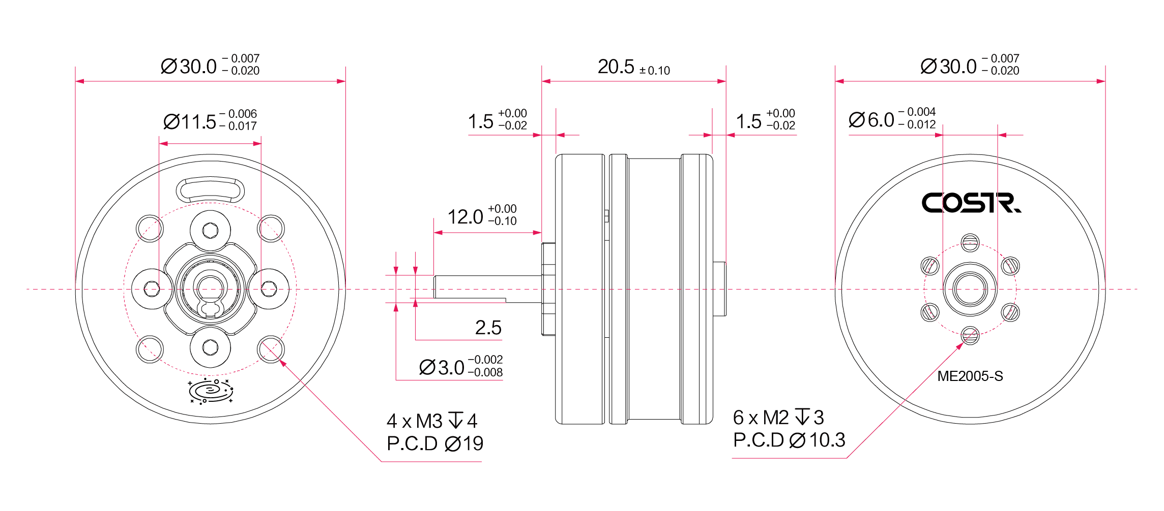
All products feature both flange output and shaft output options.

Motor Operating Parameters
Rated Voltage:
24 V
Rated Speed:
20000 rpm
No-Load Speed:
39000 rpm
Speed Constant:
6.1x10⁻⁴ V/rpm
Rated Torque:
0.18 N·m
Stall Torque:
0.76 N·m
Torque Constant:
0.005 N·m/A
Rated Current:
25 A
No-Load Current:
0.2 A
Stall Current:
140 A
Maximum Efficiency:
78.4%
Line Resistance:
0.144 Ω
Line Inductance:
0.016 mH
Mechanical Time Constant:
7.66 ms
Moment of Inertia:
30.61 g·cm²
Basic Parameters
Pole Pairs:
7
Motor Weight:
43 g
Diameter:
Φ30 mm
Length:
20.5 mm (flange); 32.5 mm (shaft)
Housing-Air Thermal Resistance:
26.5 K/W
Winding-Housing Thermal Resistance:
11.3 K/W
Winding Thermal Time Constant:
301 s
Motor Thermal Time Constant:
25.4 s
Ball Bearing Ambient Temperature Range:
-40°C to +100°C
Maximum Winding Temperature:
125°C
Typical Noise Level:
40 dB
Mechanical Data Ball Bearings
Axial Play:
3 μm
Radial Play:
2 μm
Connection Sensors
Hall Sensor 1
Hall Sensor 2
Hall Sensor 3
VCC
GND
Yellow
Green
Red
White
Black
JST
Connection Motor
Motor Winding 1
Motor Winding 2
Motor Winding 3
Yellow
Green
Red
Φ1.2
Motor Efficiency MAP

Motor Magnetic Flux Density Diagram
Through the analysis of the internal magnetic field distribution of the motor, the design is optimized to achieve the highest level of performance.

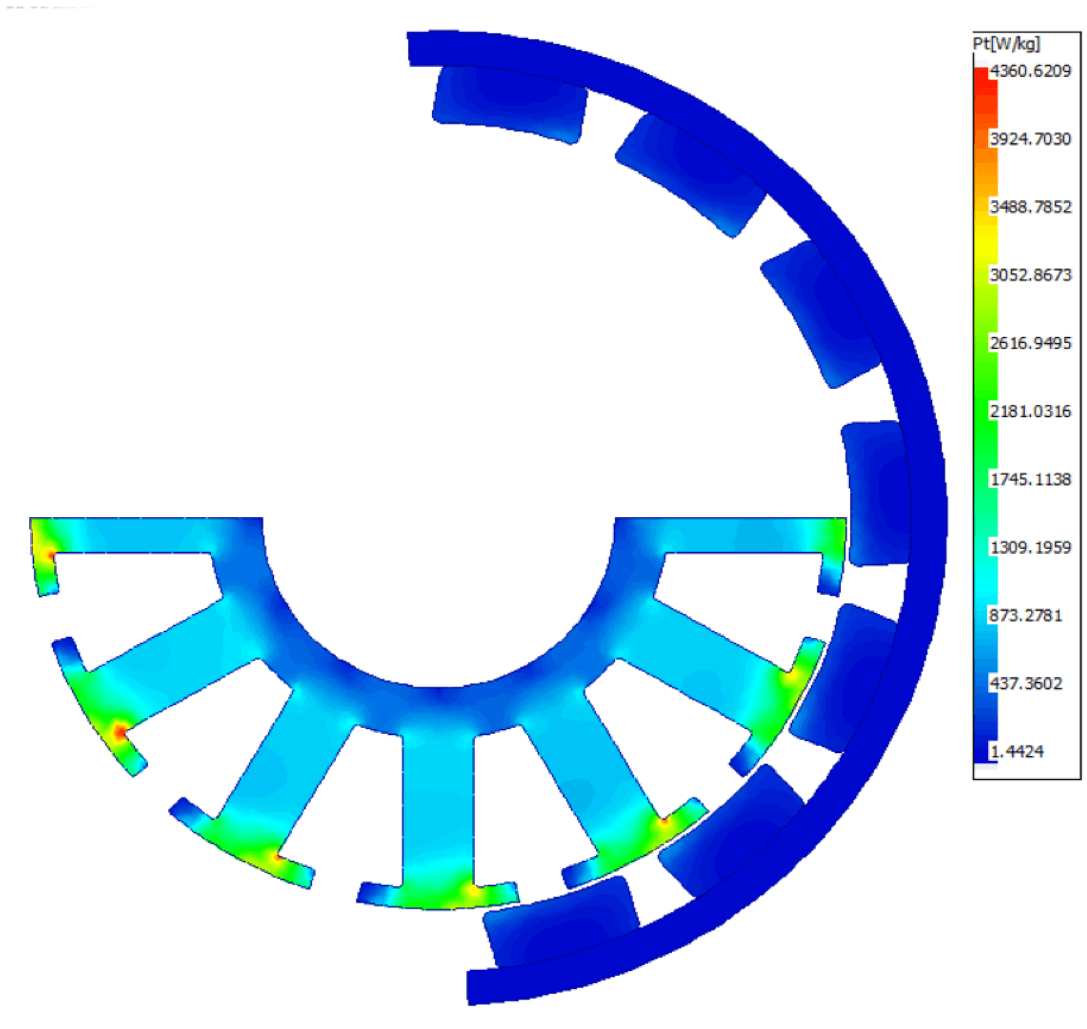
Motor Loss Contour Plot
By analyzing the distribution of iron core losses, the motor's iron core structure is optimized to minimize losses while maintaining motor performance.
Motor Back-EMF Waveform Diagram